 PRIME MOTION
The Design workspace
Prime Motion does not stop at sending G-code. It carries a parametric modeller, a CAM system, and the sender in one application — so a part can go from an idea to a cut in one place, with nothing else in the loop.
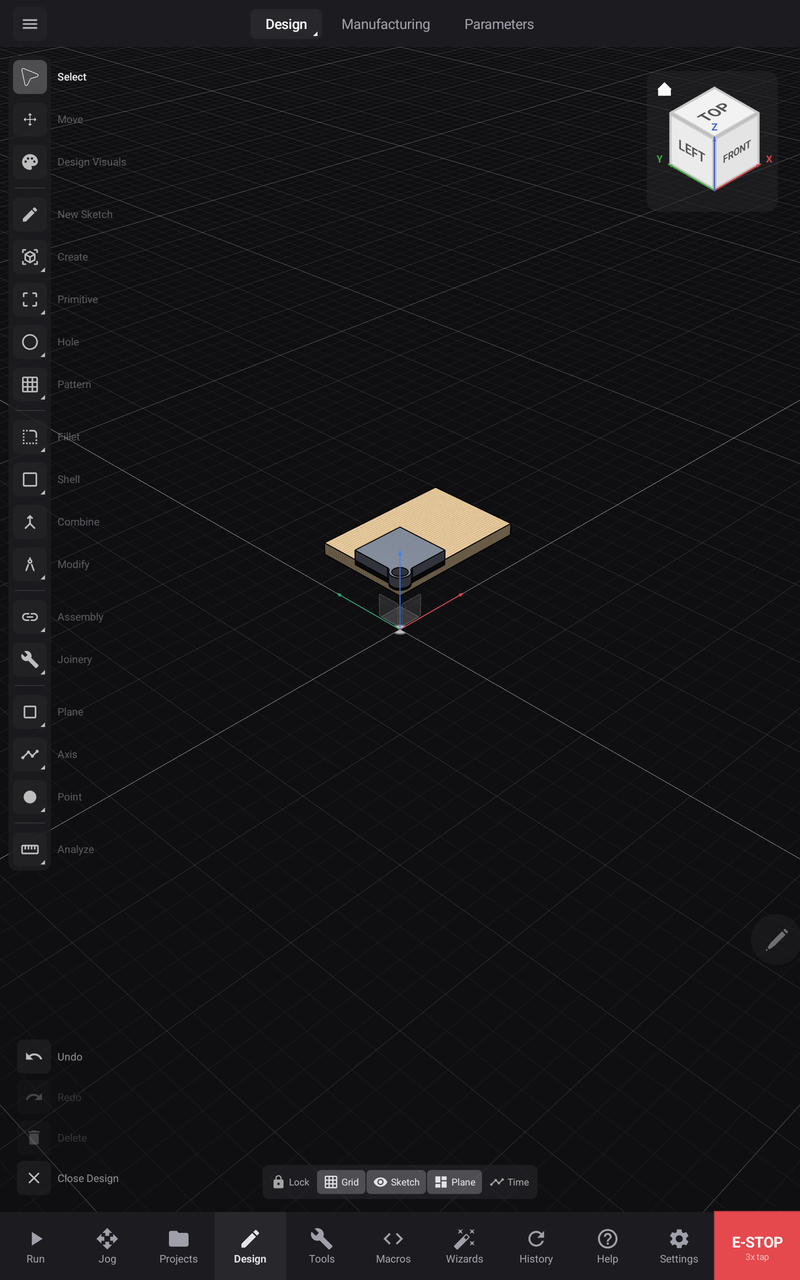
Three workspaces

| Workspace | What you do there |
|---|---|
| Design | Sketch, model, and build the part |
| Manufacturing | Turn the model into toolpaths and post a program |
| Parameters | Drive the model by named values and expressions |
They are three views of one document. A dimension changed in Parameters rebuilds the model in Design, and the toolpaths in Manufacturing follow.
The tool rail

Everything you build with is on the left, in the order you tend to need it.
| Select · Move | Pick and transform what is already there |
| Design Visuals | Appearance and display of the model |
| New Sketch | Start a 2D sketch on a plane or a face |
| Create | Turn sketches into solids — extrude, revolve, sweep, loft |
| Primitive | Drop in a box, cylinder, sphere or other primitive directly |
| Hole | Proper holes, as holes rather than subtracted cylinders |
| Pattern | Repeat features in a line, around a circle, or on a grid |
| Fillet · Shell | Round edges; hollow a solid to a wall thickness |
| Combine | Boolean operations between bodies |
| Modify | Edit existing features |
| Assembly | Relate components to one another |
| Joinery | Cut machinable woodworking joints into two bodies at once |
| Plane · Axis · Point | Construction geometry to build against |
| Analyze | Measure and interrogate the model |
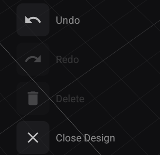
The foot of the rail carries Undo, Redo, Delete and Close Design — undo is always one reach away, not buried in a menu.
Viewport chips

Along the bottom of the viewport:
| Chip | What it does |
|---|---|
| Lock | Locks orbit and pan, so a stray finger cannot move the camera while you work |
| Grid | Shows or hides the ground grid |
| Sketch | Shows or hides sketch geometry in the 3D view |
| Plane | Shows or hides construction planes |
| Time | Opens the feature timeline |
The feature timeline

The Time chip opens the history of how the part was built — every sketch and every feature, in order. It is a real timeline, not a log: roll back to any point to see the model as it was, reorder features, suppress one to see the part without it, group related features together, and rename anything.
A feature that fails to rebuild is marked, so you can see which step broke rather than only that something did.
Drawers — how every tool works
Tools open a drawer rather than a modal dialog, and the drawer is designed so the model stays visible and live the whole time.
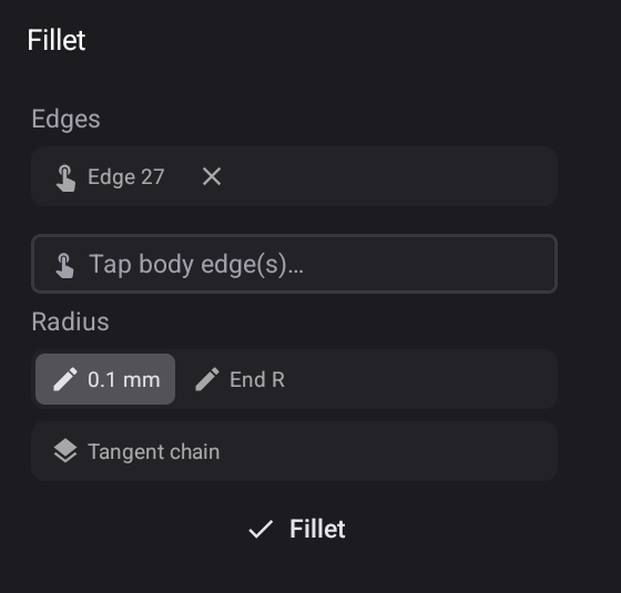
Take Fillet as the example, because it shows every part of the pattern at once.
Pick geometry with the pen. The drawer names what it wants — Tap body edge(s)… — and each thing you pick becomes a chip you can remove individually. Pick several; the field for the next one stays open.
Values are more than numbers. Fillet takes a radius, and note there are two fields: a start radius and an End R. That is a variable-radius fillet — the round can taper along the edge. Tangent chain propagates the fillet around every edge that continues smoothly from the one you picked, so you select one edge instead of thirty.
The expression keypad
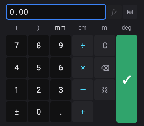
Tap any numeric field and a keypad built for this opens — not the system keyboard.
- Arithmetic in place:
+ − × ÷, parentheses. Type100/3and let it work the number out. - Units on the keypad:
mm,cm,m,deg. Enter a value in whatever unit you are thinking in. f(x)switches the field into an expression — so a dimension can reference a parameter instead of being a fixed number.- History, so a value you used a moment ago is one tap away.
Live preview, on the model
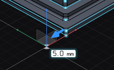
Nothing waits for OK. As you type, the model shows the result: a dimension label on the geometry itself updating with the value, and a gizmo on the affected edge you can drag directly instead of typing at all.
You are never guessing what a number will do — the part in front of you already did it. Close the drawer without confirming and nothing was changed.