 PRIME MOTION
The Run screen
Run is where a program is executed and watched. It opens on the machine's table in 3D, with the action row across the top and the viewport overlays down the left.
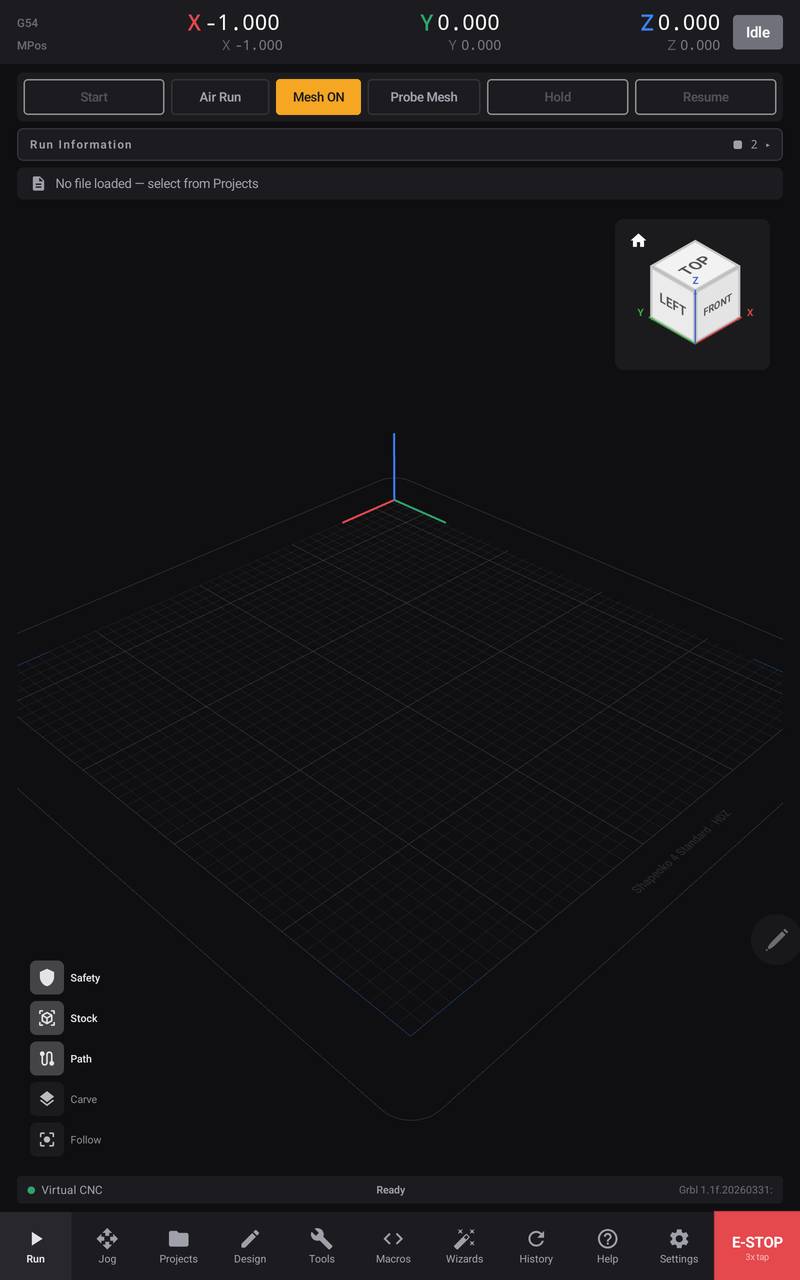
Before a program is loaded

Run does not open files itself. Programs arrive from Projects, which is also where cloud sources are browsed — see Loading a program.

Start, Hold and Resume are unavailable until a program is loaded, because each of them acts on a program. Air Run and Mesh stay available: both are setup actions rather than program actions.
While a job is running
The action row is not a fixed set of buttons — it changes with the state of the job. What you had before starting is replaced by what is useful now.

Start becomes Stop, in red. Air Run and Mesh disappear — both are setup actions, and neither is meaningful mid-cut. In their place come Overrides and Single Block.
The machine's state chip changes from Idle to Run, and the file line gains a percentage and a progress bar:

The job readout

| Field | Meaning |
|---|---|
| Lines | Lines acknowledged by the controller, out of the total in the program |
| Elapsed | How long this job has been running |
| Remaining | Estimated time left |
| Estimate | The full-job estimate, which refines as real feed rates are observed |
| Feed | The actual feed rate, with your override percentage beside it |
| Spindle | Spindle speed reported by the controller |
Overrides
Overrides appears in the action row while a job runs. It opens a drawer with the machine's three live percentages — Feed, Rapid and Spindle — and the controls to trim them, so you can slow a cut that sounds wrong without stopping it. See Feed and speed overrides. The percentage shown beside Feed in the readout is your current override, so you can always see how far from the programmed rate you are.
Overrides act on the controller in real time — the change takes effect immediately, without pausing or reloading anything.
Single Block arms line-at-a-time streaming: Step sends the next line and the machine stops when it completes, so you can walk a delicate section of the program move by move under your own hand.
Holding a job — and the decision that follows
Hold brings the machine to a controlled stop: it decelerates rather than dropping motion instantly, and stops the spindle.

The state chip reads Hold, the status bar reads Paused with the percentage reached, and the Hold button itself reports what it did — Hold • S Off tells you the spindle is off, not just that motion stopped.
This is a decision point, and both routes are open:
| Resume | Continues from exactly where it paused. The spindle is restored first — the button shows the spin-up while it happens — and only then does cutting continue. |
| Stop | Ends the job. It does not resume afterwards. |
E-STOP
The red E-STOP panel sits at the right of the navigation bar and is reachable from every screen in the app.
It takes three taps, each within a second of the last. The button brightens with each tap so you can see it arming, and if you pause between taps the count resets and you start again.
Three taps rather than one is deliberate: an on-screen emergency stop that fired on a single accidental brush would go off constantly in a workshop, and an E-STOP that cries wolf is one people learn to work around.
What it does depends on what is happening:
- With a job running, paused, changing tools or measuring a tool — the full cancel path. The job ends.
- Otherwise — a soft reset of the controller.
The table you are looking at is your machine profile, drawn
Nothing in the empty viewport is decoration. Three separate things are read straight from the active machine profile, so the picture is a check on the profile as much as a backdrop.
The grid is the travel envelope. Its extents are the profile's X and Y travel — what you see is the area your machine can actually reach.
The name on the bed is the profile's label.
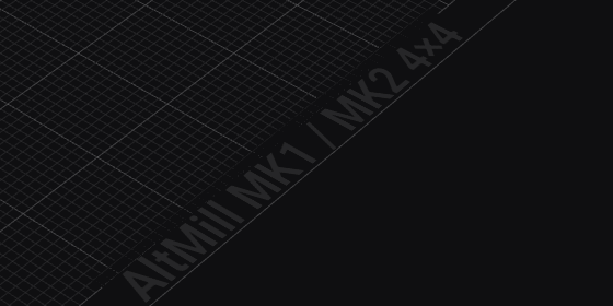
If that name is not the machine you are about to cut on, stop: every travel limit, tool-change position and safe-Z on the screen belongs to the machine named there.
The origin glyph sits at the corner your machine homes to.
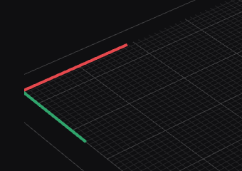
The red arm is X, the green arm is Y, and the corner they meet at is where this machine parks after a homing cycle — rear-left for an AltMill, rear-right for a Carbide, front-left for a Sienci kit, rear-right for a PROVerXL. The arms always point into the work volume, so they also tell you which way the axes count from there.
The viewport overlays
Down the left edge are the layer toggles. Every one of them is a preference, not a restriction — none can ever be disabled, and a dim one is simply switched off.
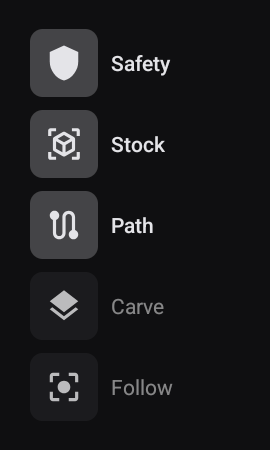
| Toggle | Shows | Default |
|---|---|---|
| Safety | The risk layer — segments of the program flagged as hazardous | On |
| Stock | The stock block the program will cut from | On |
| Path | The toolpath itself | On |
| Carve | Material simulation — the stock carved away as the program runs | Off |
| Walls | Whether the simulated cut shows its walls | On, see below |
| Follow | The camera tracks the tool instead of holding still | Off |
Carve and Follow are off by default because both are matters of taste rather than safety: Carve trades a plain view of the toolpath for a view of the material, and Follow trades a stable frame for one that chases the tool. Turn them on when you want them; nothing is gated behind them.
Three of these behave in ways the labels do not quite give away:
Safety does not draw a layer — it colours the toolpath, and the button itself is a status light. See The safety scan below; this is the most useful thing on the screen and the easiest to walk past.
Stock knows the difference between your own program and an imported one. A program posted by Prime Motion carries a STOCK header describing the real stock block, and that is what gets drawn. A hand-imported .nc has no such header, so the app falls back to a box around the toolpath's bounds, grown by the Stock Margin XY and Stock Margin Z values from Settings → General. If a stock block looks like it is merely hugging the toolpath, that is why — it is derived, not declared.
Stock and Carve both need a program. Neither draws with nothing loaded, whatever the toggle says, because both describe material being cut by a specific path.
The safety scan
When a program loads, Prime Motion reads every segment of it and checks four things before you press Start. It does not wait for the machine to get there.
| What it finds | Level | Meaning |
|---|---|---|
| Envelope violation | Critical | A move crosses the machine's soft limits |
| Z max-depth violation | Critical | A move goes deeper than the configured maximum cut depth |
| Envelope proximity | Warning | A move comes within the margin of a soft limit — 5 mm by default |
| Rapid into stock | Warning | A rapid (G0) ends below the work surface, Z=0 |
The result is reported two ways.
The offending segments are coloured in the toolpath, so you can see where in the part the problem is rather than being told a line number.
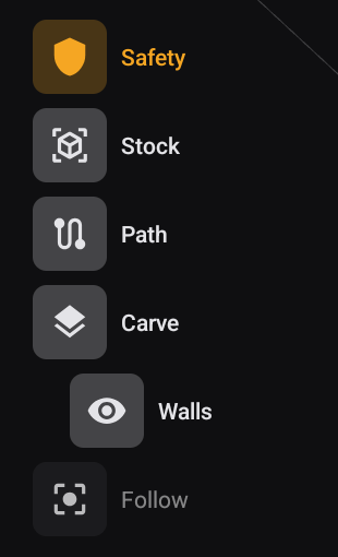
The Safety button itself changes colour to the worst thing found in the whole program:
| Safety button | Meaning |
|---|---|
| Normal | Nothing found |
| Amber | At least one warning, no criticals |
| Red | At least one critical |
The same program on a different machine
The scan is against your machine, which is easiest to see by changing machines and leaving the program alone.
2-top-surfacing.nc on an AltMill 4×4 — amber. Warnings, no criticals:
The identical file, with a LongMill 12×30 profile active — red:
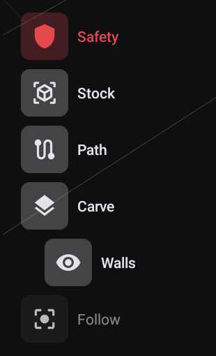
Nothing about the program changed. The part is simply larger than an 810 × 355 mm bed, so moves that were comfortably inside one machine's envelope now cross another's soft limits, and warnings become violations.
An empty bed with a file loaded
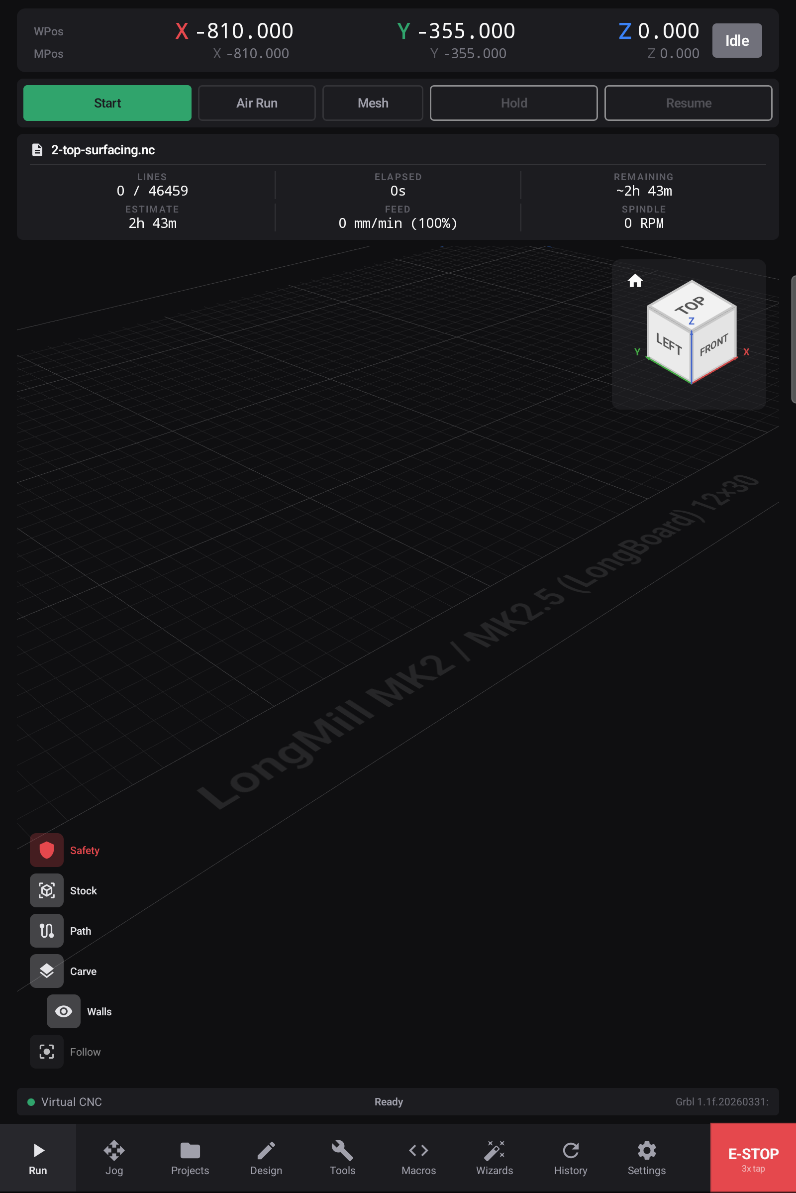
Look at that screen again. A program is loaded — the file name and its 46,459 lines are right there in the readout — and the bed is empty.
That is not a rendering fault. The toolpath is being drawn exactly where the program says it goes, and the program says it goes somewhere outside the machine's working area, so there is nothing to see over the bed.
An empty bed with a file loaded means the job is not where you think it is. There are only two reasons:
- Work zero is not set where you assume, so the whole program is offset away from the bed.
- The job does not fit this machine — the part is larger than the working area, or positioned outside it.
The cutter
A virtual cutter appears in the viewport, and it is deliberately not shown whenever the machine is merely connected and idle, or while you are jogging. It appears only while a job is active — streaming, paused, spinning up, changing tools or measuring a tool.
It is also shaped like your actual tool: the type, radius, tip angle and shaft radius come from the program's own header, so a V-bit renders as a V-bit and a ball nose as a ball nose. A file with no tool information falls back to a flat endmill.
The status bar

Three fields, left to right: what you are connected to, the machine's current state, and the firmware banner the controller reported when it connected.
The view cube
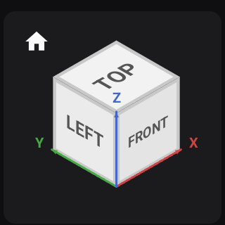
Standard orientation control — tap a face to look along it, and the house icon returns to the default view. The coloured axes are the machine's, so it also answers which way is X at a glance.
Related
- Loading a program
- Feed and speed overrides
- Mesh height maps — probed mesh points are drawn in this viewport
- Tool changes